A solar array is only as straight, as stiff and as long lasting as the structure under it. Most performance complaints we hear about on rooftop and ground mount projects, module cracking at the clamp line, water pooling at a purlin, bolts backing out after the first monsoon, trace back to how the structure was set out and tightened, not to the panels. So here is the practical sequence for solar mounting channel installation, in the order a site team should actually work through it, with the checks that matter at each stage.
As Pune based manufacturers of solar mounting structure channels, we supply channels in pre-galvanised and hot dip galvanised finishes with slotting patterns that allow cutting and joining at any point without drilling at site. That last point changes the installation method more than anything else, and we will come back to it.
Step 1: Read the layout drawing before you mark anything
Before a single hole is drilled, the team should have three things in hand: the module layout with row spacing and tilt angle, the structural drawing showing purlin and rafter centres, and the cable routing plan. The third one is the one most often missing, and it is the reason cable trays end up being fitted as an afterthought under a finished array.
Work out the following on paper first:
- Row pitch and inter-row shadow gap, so the rear leg of one row does not shade the bottom edge of the next.
- Purlin span, which decides the channel section and thickness you need. A longer unsupported span needs a heavier channel, not more bolts.
- Anchor positions relative to roof structure on rooftops, so fixings land on beams or purlins, not on unsupported sheeting.
- Cable tray route for DC strings and AC runs, including where the tray drops from array level to the inverter.
Step 2: Layout marking and setting out
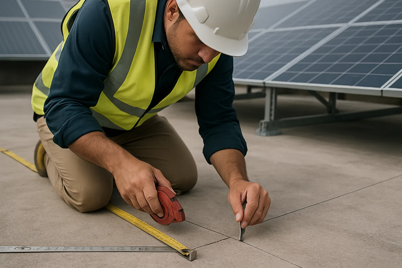
Establish one reference line for the whole array and work from it, rather than measuring row to row. On a terrace, that is usually a parapet edge or a column grid line. On a ground mount, it is the survey baseline pegged by the civil team.
The sequence we recommend:
- Snap a chalk base line along the length of the first row.
- Mark leg or pedestal centres along that line with a steel tape, always measuring cumulatively from the origin.
- Set the second row line parallel to the first at the designed pitch, then check diagonals corner to corner. Equal diagonals mean the grid is square.
- Mark anchor hole centres with a punch, not just a pencil, so the drill does not wander.
A twenty millimetre error at the first row becomes a visible dog-leg by the tenth. Fifteen extra minutes with a tape and a string line at this stage saves a day of re-drilling later.
Step 3: Anchoring, rooftop versus ground mount
This is where rooftop and ground mount solar racking channel work diverge completely.
Rooftop, RCC terrace
Base plates are typically anchored to concrete with chemical or mechanical anchors, or set on ballast pedestals where the roof waterproofing must not be penetrated. Drill to the anchor manufacturer's specified depth, blow the dust out of the hole properly (a dusty hole is the single most common cause of anchor pull-out), then fix and allow the cure time before loading. Where the membrane is pierced, seal and flash the penetration before the structure goes up, not after.
Rooftop, metal sheet roof
Fixings must land on the purlin below the sheet. Use the correct self-drilling fasteners with EPDM bonded washers and set them at the crest, never in the valley where water runs. Channels then bridge across the crests to carry the modules.
Ground mount
Legs sit on concrete foundations, driven piles or screw piles. Cast-in bolts or base plates should be set with a template so hole centres match the channel slots. Because our channels are slotted along their length, minor foundation drift can be absorbed at assembly instead of being corrected with a gas cutter and a hand drill in the field.
Step 4: Erecting and levelling the channels
Assemble legs and rafters loosely first, with bolts hand tight only. Do not final-tighten anything until the whole row is aligned. Then:
- Check leg height across the row with a water level, laser level or a dumpy level on larger ground mounts. On uneven terraces, this is where slotted adjustment earns its keep.
- Set the tilt angle with an inclinometer on the rafter, not on the module, and check it at both ends of every row.
- Check the purlin line by sighting along the row or pulling a string. Any purlin sitting high will put a point load into the module frame.
- Confirm the module plane is flat. Modules are stiff and will not forgive a twisted frame.
Think of the channel grid as the floor of a building. If the floor is out of level, every wall above it fights you. Get the plane right before you fasten it down permanently.
Step 5: Torque checks and fastener discipline
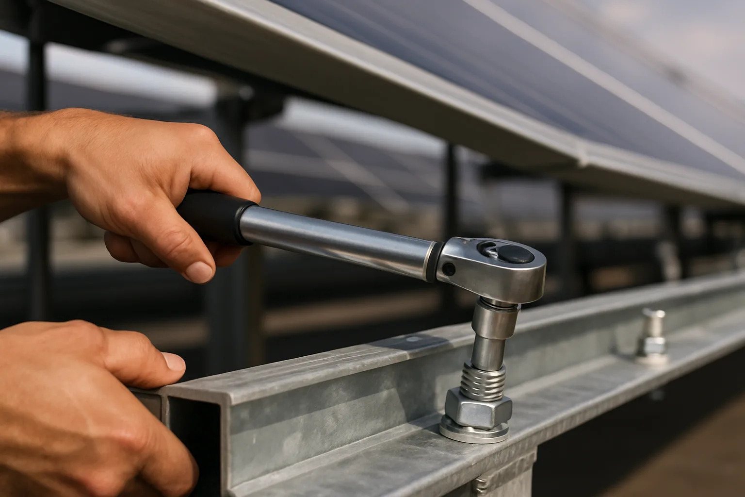
Once alignment is confirmed, tighten in a planned order: bases first, then legs to rafters, then purlins, then module clamps. Use a calibrated torque wrench and follow the torque values specified for the bolt grade and size in your structural drawing. Under-tightened bolts work loose under thermal cycling and wind flutter. Over-tightened bolts strip galvanised threads and crush washers, which then leaves a bare steel face waiting to rust.
Practical habits worth enforcing:
- Mark every torqued nut with a paint stripe. A missing stripe is visible from ten metres and makes handover inspection quick.
- Re-check a sample of fasteners after the first few weeks of service, and after the first monsoon.
- Touch up any cut edge or field-drilled hole with zinc rich paint. Hot dip galvanising to IS-2629 protects the surface it covers, not the metal you expose afterwards.
- Keep dissimilar metal contact in mind. Aluminium module frames against galvanised steel need the right clamp and washer arrangement.
Step 6: Cable management, fitted with the structure and not after it
String cables clipped to the underside of a module frame with plastic ties will fail. UV exposure, thermal movement and rodents will see to it. A rooftop solar cable tray run along the rear leg line, or a perforated or ladder tray under a ground mount row, keeps DC cabling supported, ventilated and inspectable for the plant's life.
For cable trays for solar power plants we normally suggest ladder or perforated trays in hot dip galvanised finish for outdoor runs, sized so cables sit in a single layer where possible for heat dissipation. Our ladder cable tray range suits the long spans between inverter stations, while perforated cable trays work well for shorter array-level runs where you want cleat support along the base. Fix tray brackets to the same channel grid you have just levelled, using the existing slots. That is far quicker than drilling a finished structure.
Common installation mistakes we get called about
- Marking rows individually instead of from a single baseline, giving a visibly crooked array.
- Fixing sheet roof fasteners in the valley, then chasing leaks for the next two years.
- Final-tightening one row completely before checking the next, leaving no adjustment left.
- Field cutting channels and leaving the raw edge unpainted.
- Selecting a channel thickness on price alone, then adding extra legs to compensate for deflection.
Choosing the right solar mounting channel manufacturer for your project
Installation quality depends heavily on what arrives on site. As a solar mounting channel manufacturer operating from Burhani Industrial Area in Pune since 2001, we fabricate our own 'Hutaib' brand solar mounting channels along with hi-tech channels, unistrut channels and GI lintels, all through in-house manufacturing, quality control and packing units. Channels are supplied pre-galvanised as per IS-277, hot dip galvanised as per IS-2629, powder coated or in stainless steel grades, as per customers' demands.
We also make custom made channels and accessories through our in-house R&D where a roof grid, wind zone or foundation layout does not suit standard lengths. If you want to compare finishes before you specify, our note on galvanized versus aluminium solar mounting channels covers the trade-offs, and the solar mounting channel page lists sizes and thicknesses.
Send us your array layout, tilt angle, span and site location and we will advise on section, thickness and finish, then quote for supply to Pune, Mumbai, anywhere in India or for export. You can reach our team through the contact page for drawings, specifications and prompt delivery schedules.
Frequently asked questions
What is the correct sequence for solar mounting channel installation?
Read the layout and structural drawings, set out from a single reference baseline, anchor the bases, erect the frame with bolts hand tight, level and set the tilt, then torque tighten in order from base to module clamps. Cable tray brackets should be planned into the same grid. Working in this order leaves adjustment available until the alignment is confirmed.
How do rooftop and ground mount installations differ?
Rooftop work is dominated by the anchoring method and waterproofing, chemical or mechanical anchors on RCC, ballast pedestals where the membrane cannot be pierced, or crest-fixed fasteners on metal sheet roofs. A ground mount solar racking channel sits on concrete foundations or piles, so the main challenge is foundation position tolerance and levelling across uneven ground. The levelling and torque discipline is the same for both.
Why do slotted channels make site installation faster?
Our slotting patterns allow cutting and joining at any point without drilling at site. That means minor foundation drift, uneven terrace levels and bracket positions for cable trays can all be absorbed at assembly, instead of being corrected with field drilling that damages the galvanised coating.
Which cable tray should be used with a solar array?
For outdoor DC and AC runs we generally suggest ladder or perforated trays in hot dip galvanised finish as per IS-2629, sized so cables sit in a single layer for ventilation and heat dissipation. Ladder trays suit long runs between array and inverter stations, while perforated trays work well for shorter array-level routes.
Do you supply solar mounting channels outside Pune and Mumbai?
Yes. We are manufacturer, supplier and exporter of cable trays and channels from Burhani Industrial Area, Pune, and we supply across India as well as to export markets worldwide. Send your layout and quantities through our contact page for a quotation and delivery schedule.