To specify solar mounting structure channels, you need to define four things: the channel profile, the steel thickness, the protective coating and the fasteners. Each choice depends on whether the array is rooftop or ground mount, the span between supports, the wind exposure of the site and how corrosive the environment is. A purchase order that fixes all four, backed by a structural design, avoids substitutions, site rework and early corrosion.
This guide explains how electrical engineers, EPC contractors and procurement teams can write a clear, buildable specification, drawing on our experience as a Pune-based manufacturer, supplier and exporter of cable management and support systems since 2001.
What a Solar Mounting Structure Channel Specification Must Cover
Solar mounting structure channels are the purlins, rails and bracing members that carry PV modules from the roof or foundation up to the clamps. A vague line item such as "GI channel for solar" invites suppliers to quote the lightest section available. A complete specification should state:
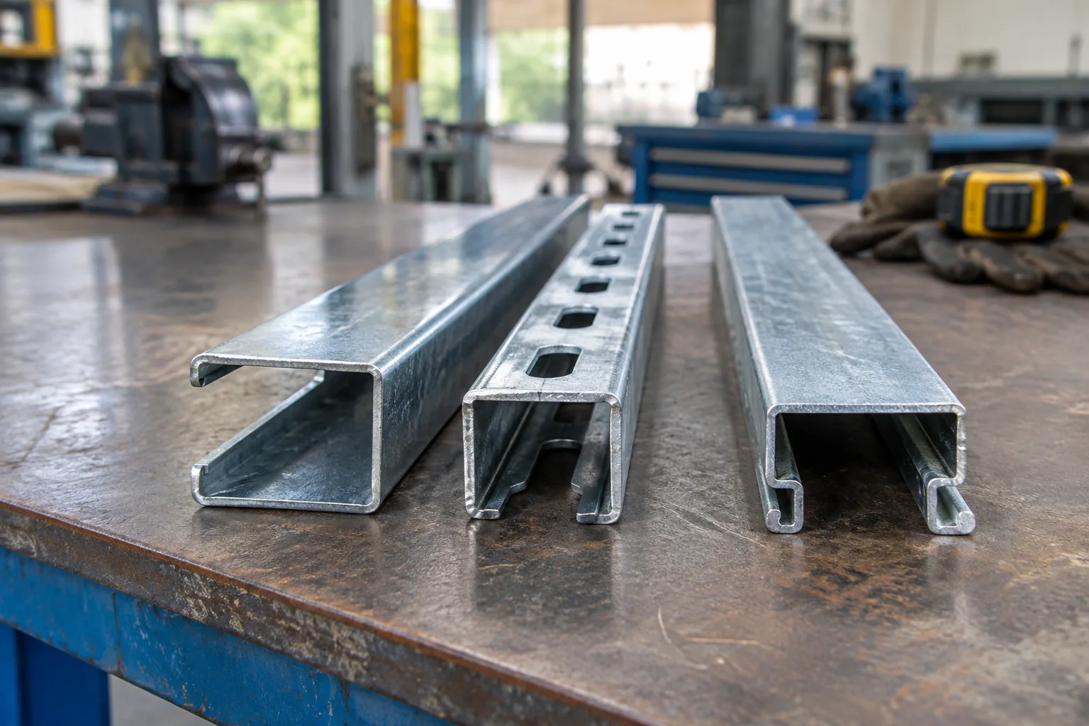
- Profile: section type and dimensions (C, lipped C, slotted strut or custom shape)
- Material, thickness and finish: steel grade, sheet thickness and coating standard
- Slotting and hole pattern: to match module clamps, brackets and site adjustment
- Lengths: standard or cut-to-size, with tolerance on length
- Fasteners: bolt, nut, washer and channel nut material and finish
- Packing and marking: bundle identification for large project deliveries
You can see how these parameters come together in our solar mounting channels, which are manufactured, inspected and packed in-house.
Choosing the Channel Profile
The profile governs stiffness more than any other factor. For the same weight of steel, a deeper section resists bending far better than a shallow one, which is why profile selection comes before thickness.
Lipped C channel
The lipped C is the most common purlin profile in rooftop and ground mount solar structures. The return lips stiffen the open edges and provide a positive grip for channel nuts and clamps.
Slotted strut channel
Continuous-slot strut channels allow modules, brackets and bracing to be fixed at any point along the length without drilling at site. This is valuable on rooftops where obstructions, parapets and service ducts force layout changes. Our galvanised Hi-Tech slotted C channels are often used for this kind of adjustable framing.
Custom profiles
Large ground mount projects sometimes justify a project-specific profile optimised for the module layout. Through in-house R&D we develop custom sections and slotting patterns against customer drawings, so the channel suits the actual table design rather than forcing the design around a catalogue item.
Steel Thickness: Sized to Span, Load and Wind
Thickness should never be chosen by habit or price alone. The correct gauge follows from a structural check of the array, which considers dead load of the modules, the support span, tilt angle and, above all, wind load.
In India, wind loads on structures are calculated using IS 875 (Part 3), the Bureau of Indian Standards code for wind loads on buildings and structures. It accounts for basic wind speed by location, terrain category, height and the topography of the site. A rooftop array on a tall building near the Mumbai coastline faces very different design pressures from a low ground mount table on the Deccan plateau around Pune, even if the module count is identical.
Practical points for buyers:
- Ask your structural consultant to state the minimum thickness and section on the drawing, not just "as per design".
- Remember that thickness is measured on base steel; the coating does not add structural strength.
- Increasing the support span almost always demands a heavier or deeper channel, so compare the cost of extra posts against heavier purlins.
- Specify a thickness tolerance and verify it at inspection, since undersized sheet is a common cause of sagging rails.
For projects in exposed locations, our article on solar mounting channels for high-wind and coastal projects covers the additional design considerations in detail.
Coating: Pre-Galvanised IS-277 vs Hot Dip Galvanised IS-2629
Solar structures are expected to stay outdoors for the full life of the plant, so the coating decision directly affects lifecycle cost. We manufacture to two Indian standards:
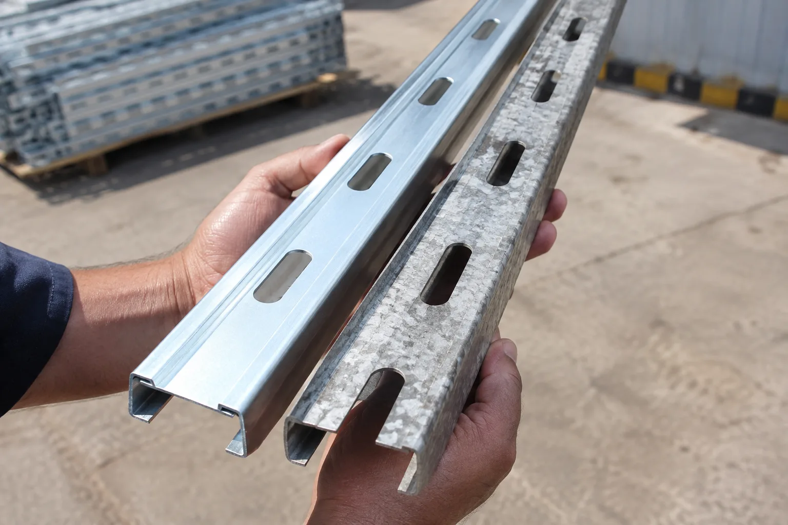
- Pre-galvanised to IS-277: IS 277 covers galvanised steel sheet. The zinc coating is applied to the coil before forming and slotting, so cut edges and punched holes have limited protection. Pre-galvanised channels suit sheltered rooftops and moderate inland environments.
- Hot dip galvanised to IS-2629: IS 2629 is the Indian recommended practice for hot dip galvanising of iron and steel. The finished channel is galvanised after fabrication, so edges, slots and holes are coated along with the faces. This is the usual choice for ground mount plants, industrial rooftops and humid or coastal sites.
Stainless steel (SS 304 or 316) is reserved for highly corrosive locations or critical components. Aluminium is another option; our comparison of galvanised and aluminium solar mounting channels explains where each material makes sense.
Fasteners and Hardware
Fasteners are frequently the first part of a solar structure to corrode, because they are small, cheap and often bought separately from local stock. Specify them with the same care as the channels:
- Match the protection level: hot dip galvanised channels should be paired with hot dip galvanised or stainless steel fasteners, not plain zinc-plated bolts.
- Avoid galvanic corrosion: where aluminium rails meet steel channels or stainless steel bolts, use isolation washers as recommended by the structural designer.
- Use locking hardware: spring washers or locknuts help resist loosening caused by wind-induced vibration.
- Specify channel nuts to suit the profile: the nut must engage the channel lips correctly to carry the design load.
Rooftop vs Ground Mount: How the Specification Changes
Rooftop arrays
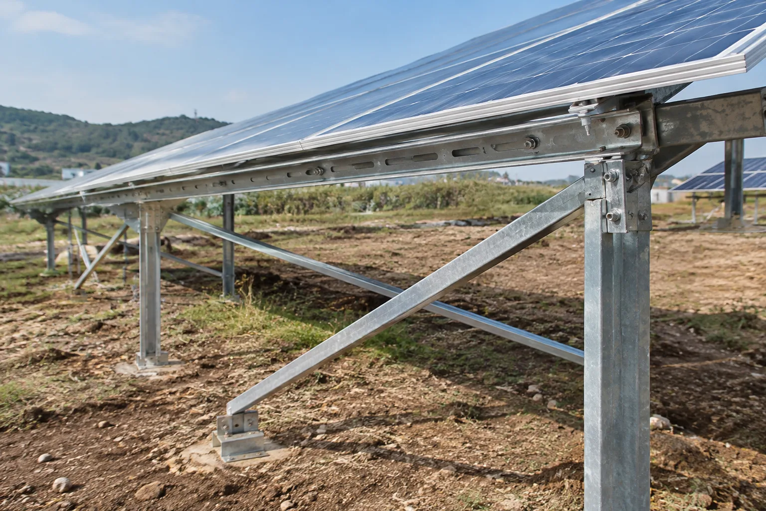
Rooftop structures are weight-sensitive and must respect the existing roof. Slotted channels that can be adjusted on site, lighter sections over short spans and attachment details compatible with the roof sheeting or RCC slab are the priorities. Waterproofing at anchor points is equally important.
Ground mount arrays
A ground mount solar racking channel typically carries longer spans and greater wind exposure, and is in contact with dust, moisture and sometimes saline soil near its base. Hot dip galvanising to IS-2629, heavier sections and consistent hole patterns for fast, repetitive assembly across hundreds of tables are standard expectations. Our step-by-step solar mounting channel installation guide shows how these components are assembled on site.
Planning Cable Routing Alongside the Structure
DC string cables and AC runs need support too. Specifying a rooftop solar cable tray in the same finish as the mounting structure keeps corrosion protection consistent and lets cable supports be fixed directly to the channels. Perforated trays with covers protect cables from direct sun, while ladder trays suit heavier runs to inverters. Coordinating both in one order simplifies procurement and ensures fittings align.
A Practical Specification Checklist
- Obtain a structural design with wind loads per IS 875 (Part 3).
- Fix the profile and dimensions for purlins, rafters and bracing.
- State minimum base steel thickness and tolerance.
- Choose the coating: IS-277 pre-galvanised or IS-2629 hot dip galvanised.
- Define slotting and hole patterns against clamp and bracket drawings.
- Specify fastener material, finish and locking method.
- Include matching cable trays and accessories in the same package.
- Agree inspection, packing and marking requirements before dispatch.
As we tell every project team, "Selecting the right support system depends on load, installation environment, support spacing, material and required finish." Getting those decisions on paper is what separates a durable array from a costly retrofit.
Work with a Solar Mounting Channel Manufacturer
Hutaib Electricals manufactures solar mounting structure channels, Hi-Tech channels, cable trays and accessories from Pune for projects across Maharashtra, the rest of India and export markets including the UAE, Nepal, Bangladesh and Bhutan. For bulk requirements or custom fabrication, share your drawings, specifications and required quantities with our team to request a quotation.
Frequently asked questions
Which coating is better for solar mounting structure channels, pre-galvanised or hot dip galvanised?
Pre-galvanised channels to IS-277 are suitable for sheltered rooftops and moderate inland environments. Hot dip galvanised channels to IS-2629 are coated after fabrication, so slots, holes and cut edges are protected too. For ground mount plants, coastal and humid sites, hot dip galvanising is the usual choice.
How do I decide the steel thickness for solar mounting channels?
Thickness should come from a structural design that considers module weight, support span, tilt and wind load calculated as per IS 875 (Part 3). Ask your consultant to state the minimum section and base steel thickness on the drawing. We can then manufacture to that specification.
Can you manufacture custom solar mounting channels to our drawings?
Yes. Hutaib Electricals develops custom profiles, lengths and slotting patterns through in-house R&D and manufacturing in Pune. Share your drawings, finish requirement and quantities, and our team will review them for a quotation.
Do you supply solar mounting channels outside Pune and Mumbai?
Yes. We supply across Maharashtra and pan India, and export to markets including the UAE, Nepal, Bangladesh and Bhutan. Bulk project orders are packed and marked in-house for dispatch.
Can I order cable trays along with the solar mounting structure?
Yes. We manufacture perforated, ladder and wire mesh cable trays with matching accessories in the same finishes as our solar channels. Ordering them together keeps corrosion protection consistent and simplifies site coordination.